Wires
 |
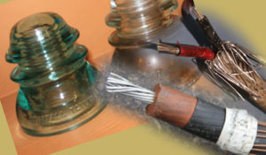
Wires as we define here are
used for transmission of electricity or electrical signals. Wires
come in many forms and are made from many materials. They may seem simple but engineers are
aware of two
important points:
-Electricity in long wires used in transmission behaves very differently than in short
wires used in design of devices
-The use of wires in AC circuits brings on all sorts of problems like
skin effect and proximity effects.
1. Resistivity/Impedance
2. Skin Effect
3. Types of Wire Design
4. More on Wire Materials
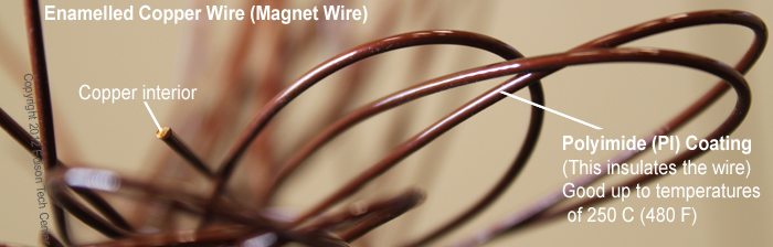
5. Wire Insulation
1.) Behavior of electricity in wires: Resistance and Impedance
It's important to know if you are dealing with DC or AC power in a given wire. AC power has some very complex physics which cause some strange effects. This was one of the reasons why AC power was developed in the 1890s, long after DC power. Engineers like C.P. Steinmetz had to figure out the mathematics and physics first.
AC Power:
In AC power current likes to travel near the surface of a wire (skin effect). AC power in a wire also causes a magnetic field to form around it (inductance). This field effects other nearby wires (such as in a winding) causing proximity effect. All of these properties must be dealt with when designing an AC circuit.
DC Power:
In DC power current travels through the whole of a wire.
Size of the conductor and material (AC and DC power):
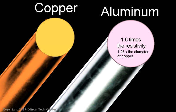
Electricity travels more easily in highly conductive elements like copper, silver or gold, the less conductive the material, the larger the diameter has to be to carry the same current load.
Engineers choose the right wire diameter for the job, raising current in a wire increases the resistivity and generates more heat. As you'll see in the diagram below copper can carry more current than aluminum while carrying the same load.
 |
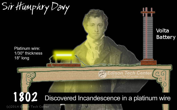
Below: When Sir Humphrey Davy put lots of current through a thin platinum wire in 1802 it glowed and made the first incandescent light! but just a few seconds later the wire melted and vaporized due to the heat caused by resistance in the wire.
 |
Quality of Material: Impurities and Crystals:
Most materials have impurities.
In copper the oxygen content and other materials in the copper effect the conductivity,
so copper which will be made into an electrical wire is alloyed differently
than copper which on it's way to becoming plumbing.
Metals are crystalline (as you'll see in our Copper video).
Monocrystalline copper or aluminum has better
conductivity than polycrystalline metals, however large crystal copper is very expensive to
produce and only used in high performance applications.
Resistance in a wire the describes the excitation of electrons in the wire's conductor material. This excitation results in the creation of heat, and loss of efficiency. In early DC power Thomas Edison couldn't send his power a long distance without using wide-diameter copper wires due to resistance over distance. This made DC power not cost effective and allowed for the growth of AC power.
Measurement Tools:
Engineers use Ohms Law to calculate how much resistance a given wire will have. This tells us how much energy we will loose over distance.
I = V / R Amps = Volts divided by Resistance
Formulas for Resistance and Conductance:
Resistance = resistivity / cross sectional area
Conductance = 1 / Resistance
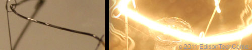
When Resistance is Good:
Creation of heat in a wire is normally a sign of wasted energy, however in a tungsten or tantalum wire the heat makes the wire glow and produce light which may be desired. Tungsten is used to make filaments because it has a very high melting point. The wire can get very hot and glow brightly without melting. Tungsten would be very bad for power transmission since most of the energy put through is lost in the form of heat and light.
 |
In power
transmission we look for the lowest resistivity possible, we want
to transmit power over long distances without losing energy through heat.
We measure resistance in a wire by ohms per 1000 feet or meters.
The longer electricity has to travel, the more energy it looses.
Superconducting Wire and Resistance:
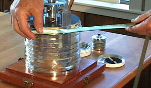
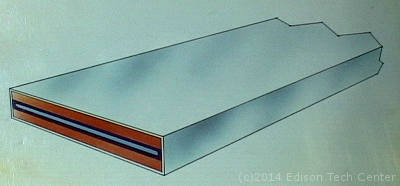
 |
Above: Superconducting wire can be made into a metallic "tape" |
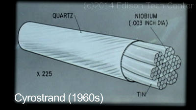
Above: Carl Rosner , Mark Benz and others
used special superconducting wire coils to produce the world's
first 10 Tesla magnet. Niobium and tin are used instead of copper
since materials work differently at different temperatures.
One great solution to power transmission is superconductors.
As a metal becomes super cold (approaching absolute zero) it obtains a
conductivity of infinity. At a certain point there is no resistivity at all.
There have been experimental superconductive high voltage lines which
were able to transmit power with almost no losses, however the technology
is not developed enough to be cost effective.
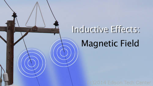 |
Magnetic Fields (inductance and impedance):
Every wire used to transmit AC power creates a magnetic field while current flows through it. The
magnetic field is visualized by concentric rings around the cross section
of the wire, each ring closer to the wire has a stronger
magnetic power.
Magnetic fields are useful for making very strong magnets (when in a coil) i.e. making motors
and generators, however these magnetic fields are unwanted in power transmission lines.
While resistivity of a wire can impede the flow of current and make heat, the inductance of
a wire/transmission line can also impede the flow of current but this impedance
does not create heat since the energy is 'lost' in creating a magnetic field rather
than exciting electrons in the material. This impedance is called Reactive impedance in AC
Circuits. We used the word 'lost' however the power is not truly lost, it is used to create the magnetic
field and it returns when the magnetic field collapses.
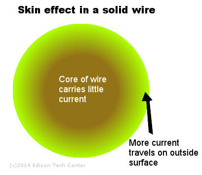
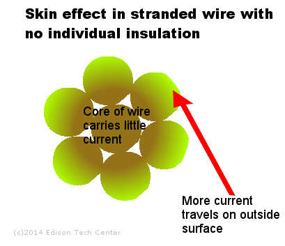
2.) Skin Effect:
In AC power electrons like to flow on the outside of a wire. This is because the changing of current back and forth causes eddy currents that result in current crowding toward the surface.
Skin Depth
Skin depth is a fixed number for given frequency, resistivity and permittivity. The higher the frequency of AC power in system, the more current is compressed on the outside of the wire, so a wire that is used at 60 Hz at a given voltage will not be ok at 200 MHz. Engineers must always have the skin effect in mind when designing circuits. See the wikipedia site for the formula used to calculate the skin depth.
 |
 |
|
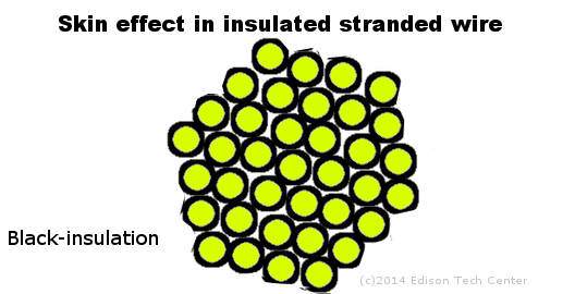
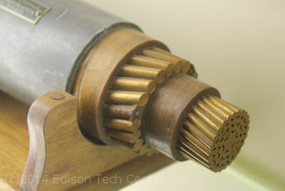
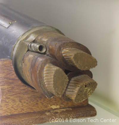
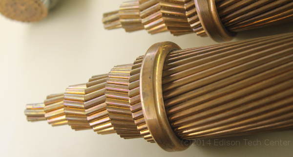
Above: engineers overcome skin effect by by using insulated stranded wire.
If you make the individual strands equal to one skin depth, most of the current flows in the entire
cross section and you use all of the copper. The downside is your wire must have a larger
diameter as you need all the extra space for insulation. As the wire strands get smaller
in diameter, and the insulation stays the same thickness, the ration of copper area
to insulation can become less than one, then you will have more insulation than
copper in the winding or cable.
|
|
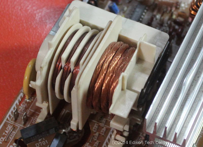
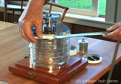
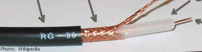
Below: Higher frequency AC = less skin depth. The 'faster' current alternates back and forth
the more eddy currents it creates. This high frequency
power supply operates in the MHz range, notice the special wire used on
the right. The wire appears to be stranded and bare, but it is not,
it has a clear enamel coating insulating it, so each small strand of wire
carries it's own part of the current, with current traveling on the outside
of each strand. This gives more surface area as a whole and allows for
a large amount of current to travel through.
|
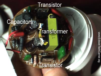
Above: Compact fluorescent light electronics, the transformer is very small and is designed very cheaply. These parts often fail before the end of the typical life cycle of the unit.` |
|
|
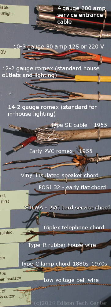
3.) Types of Wire:
WIRING 1880s to Today:
|
|

Below: Video on types of wire used by electric utilities:
|
4.) Wire Materials:
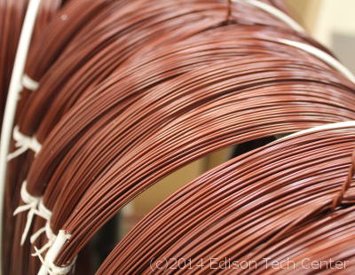
The most common material for electrical wire is copper and aluminum, these are not the best conductors however they are abundant and low cost. Gold is also used in applications because it is corrosion resistant. Gold is used in automobile airbag electronics to guarantee that the device will function many years later despite exposure to harmful elements.
|
Above: gold used in connectors for Motorola chips |
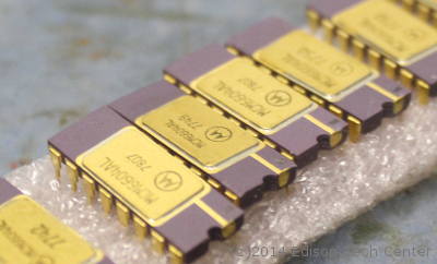
Gold is usually used in contact areas because this point in the system is more exposed to corrosion and has more potential for oxidization.
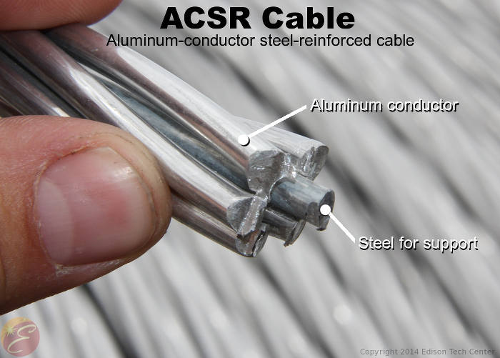 |
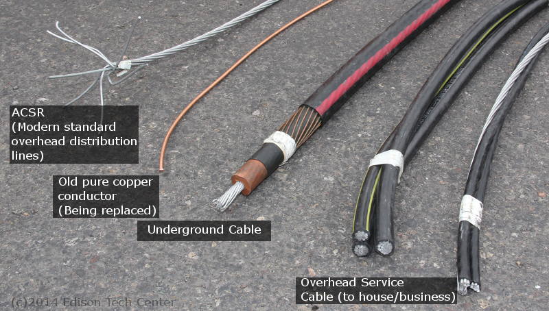
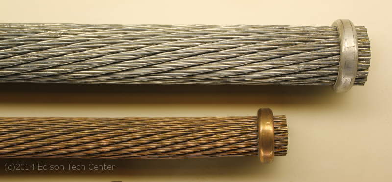
Aluminum
wrapped around a steel center wire is used in power transmission because
the aluminum is cheaper than copper and doesn't corrode. The steel center
is used simply for strength, to hold the wire over long spans. Above is
a typical ACSR cable used in overhead powerlines around the world.
Good conductors which are a
solid at room temperature:
Platinum, Silver, Gold, Copper, Aluminum
 |
|
|
Article, photos and videos by M.Whelan and W.Kornrumpf
Sources:
Georgia State University
Wikipedia
Wizards of Schenectady Carl Rosner. Edison Tech Center. 2008
Interview with Rudy Dehn. Edison Tech Center. 2012
Video with Denver Electric Motor. Edison Tech Center. 2012
Video with San Miguel Power Association. Edison Tech Center. 2014
William Kornrumpf, Electrical Engineer