

Amplifiers
Electronic amplifiers or "amps" are devices that increase signal power. They are used in everything from radio to computers. Understanding amplifiers is key if you want to be an electrical engineer or simply learn to tweak your audio system. Thousands of engineers have contributed to better amplifier design over the years, we will mention just a few here. The area of amplifier design is huge, so we'll only cover some basics here with links to pages that go into more details on aspects of this topic.
1.) How they work and basics
2.) Power amplifiers
3.) Amplifiers for speakers and music instruments
4.) Transistor amps
5.) Tube amps, how they work
6.) 3 Tube amp model
 |
 |
1.) How They Work
In the most basic sense an amplifier takes a weak signal and adds power from a power supply to it to make it larger at the output end.
Two basic examples of the need for an amplifiers:
Audio - Thomas Edison and Emile Berliner developed the carbon microphone.
DC power
passes between two metal plates with carbon in between, one of those plates is the diaphragm
that vibrates when soundwaves strike it. This changing distance between the two plates
changes the resistance
and thus on the output end you have a DC signal that becomes AC as it modulates.
Problem: the output end of a microphone is a weak signal because low DC voltage is needed to make
a microphone work. Now we need to take that weak signal and either send it over long distance
(like the telephone system) or put it into a loudspeaker. Amplifiers were needed to do this.
Radio - When Alexanderson, Fessenden, Hull and others developed voice radio transmission and radar they needed a way to take the weak radio waves detected by vacuum tubes and amplify the signal so it could power a speaker. Amplifiers (like the triode vacuum tube) were also needed to take weak signals carrying audio and video (television) and turn that signal into either megawatts of signal (for a transmitter), or several watts to power a loudspeaker on the receiver end.
PrerequisitesIn order to really understand how amplifiers work and tinker with them yourself you'll need a background in certain areas of electronics. Most engineers begin their life-long passion for the field by tinkering (experimenting with actual devices). If you combine book knowledge with tinkering and safe practices you can master the workings of amplifiers. The most common way to start working in this area is to build your own audio systems, at home or for your car. Amplifiers are very dangerous to work with, the current and voltages involved can kill you so it is important to not work on a powered system and follow safety rules. Even when not plugged in a capacitor can store lots of energy in the system. |
Here are some terms you would read about before playing with amplifiers:
Voltage |
Gain - the word gain is used to describe the amplifiers ability to multiply power. To measure gain you need to measure input and output power. Decibels are used to measure gain through equations. Gain is logarithmic, measured by the power of 10. To calculate the gain of a given amplifier use the series of equations found on this wiki page >
Oscillators - when an amplifier is connected to a filter and then back to its own input you create a linear oscillator. Oscillators are used in clocks, radio, television, filters, and many other things. They are used to tune circuits, and are important tools for making things operate. More on oscillators >
2.) Power Amplifiers
In the chain of signal the power amplifier refers to the final amplifier. The power amplifier may boost signal to high levels for use to power an antenna, magnetron(radar), loudspeaker or long distance data transmission wire/fiber.
Power amplifiers come in classes to describe how much of the sinusoidal signal is amplified.
The amp can be designed to be turned off for half of a cycle, which changes the wave form coming
through.
Classes (analogue): A, B, AB, C
Classes (digital): D, E, F, G, S, T
Read more about classes here.
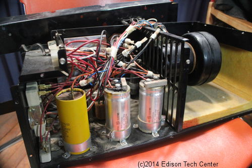
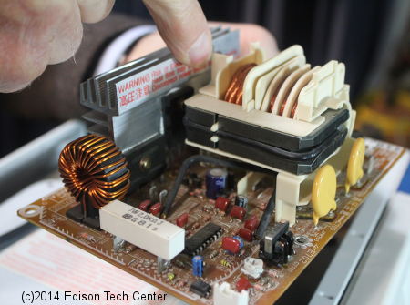
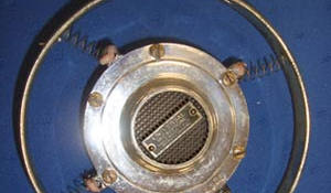
Below: Right: modern solid-state amplifier for a magnetron.
 |
 |
To make an operational amplifier you use multiple transistors along with resistors and capacitors, this way you can amplify a range of frequencies. By applying both negative and positive voltages to the device you can have the amplifier create up to 12 volts(+) with 12 volts(-), this way you have enough power to make a speaker work. There are a 1000 ways to design these circuits but you can start with a few basic models.
Capacitor used before the transistor: transistor amplifiers use a capacitor before the input of the transistor in order to 'center' the DC signal coming from a microphone. Microphones resonate, creating negative and positive DC energy. They also use a 'bias' but for a different reason than transistors. The bias in the microphone energizes the device and puts 0 db up above 0 voltage. The bias in most microphones requires you to supply it with about 2 volts, but it can be different. The capacitor before the transistor brings the 2 volt bias down to actual 0, and therefore removes the DC offset. The transistor needs this to work.
Complications: Creating an amplifier circuit gets complicated due to things like signal noise. We recommend you start building simple amplifiers from kits in order to get the basics down. Than after that you can tweak more powerful and expensive systems.
Learn through building:
Build your own amps and effects pedals (has simple kits available) >
Vintage Vacuum Tube Amp Kits (full size
guitar amps with speakers) >
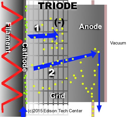 At (1.) the grid is negatively charged and repels electrons, possibly even blocking them completely from reaching the cathode. At (2.) the grid is not negatively charged and electrons freely pass through to the curved outer plate which is the cathode. Note: part (1.) and (2.) are not happening at the same time, they are only shown together for this graphic. |
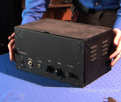
5.) Using vacuum tubes to amplifyThe advent of the triode in 1906 revolutionized telephone and radio. There are many kinds of vacuum tubes used to amplify and we still use some of them today. Tube amps may use tetrodes, triodes and pentode vacuum tubes to do the job of signal amplification. The triode amplifier: This tube has a hot cathode in the center surrounded by a metal grid with the anode surrounding that. The cathode emits electrons, and in the vacuum electrons freely flow through the grid to the anode. By energizing the grid negatively you repel more electrons, this means that less electrons can pass through the grid to get to the anode. If you take weak audio signal (a varying voltage) and apply it to the grid, you'll be letting more power through the grid during positive spikes and less on negative, thus you can greatly amplify the signal. The bad part about tube amplifiers is that they consume more power and space than transistors. The hot cathode in a tube is made of a tungsten and thorium filament. This filament, just like a lightbulb will burn out after a number of hours and the tube will have to be replaced. When you attach an amplifier to a speaker the amplifier's behavior will change. Loudspeaker impedance will change as the load changes, and this effects the entire system. Advantages over transistors:Guitarists will argue that sound from a tube amplifier is better than that from transistor-based amplifiers. Tube amp systems have non-linear clipping and more second-order harmonic distortion, there are plenty of detailed articles out there on this subject. Solid state amplifiers designed for guitarists now use current feedback circuits to increase the output impedance, this gives a similar sound from the speaker that a tube amplifier would. |
6.) Three Tube Amplifier Example
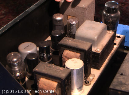
We will use a simple guitar amplifier with three tubes to demonstrate how the signal is transformed from a weak 0.9 volt signal to a powerful signal enough to power a large speaker diaphragm. Our graphics are a simplified version of the Fender Champ-Amp featured in "Uncle Doug's" videos. See the 38 minute video listed at the bottom here to go into more depth if you need. In our diagrams below we have omitted resistors and most capacitors in order to focus on the action of amplification.
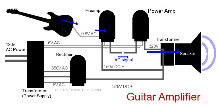
In the graphic above you'll see the layout which consists of a power supply (transformer) connected to a rectifier tube and two other tubes. The transformer converts 120 V from the wall into three separate lines. The 6V line just powers the filaments in the two amplifier tubes. It keeps the filaments hot so the tubes can work. The 5 V line goes to the power rectifier and warms up that tube. The other high voltage line takes AC power to the rectifier where it is converted to DC by chopping off the negative sides of the wave form. Resistors and transformers elsewhere in the system help smooth out the DC signal, removing the curved humps.
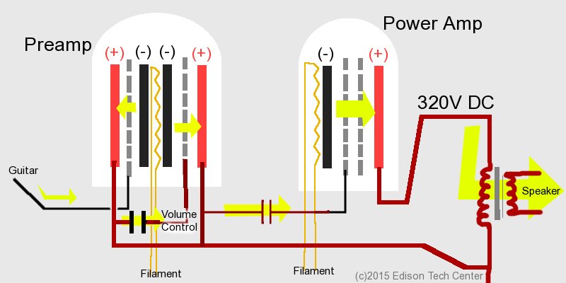
The guitar signal generated by the pickups is connected to the grid in the pre-amp triode tube. The anode in the tube has been supplied with a very strong 150 volts of + DC. So that plate really puts a pull on any nearby negative ions (electrons). On the cathode in the center of the tube it is very hot stimulating the generation of lots of electrons, however the grid is by default in a negative state, blocking the passage of electrons over the anode. The AC signal from the guitar changes the grid, allowing millions of electrons to stream over to the other side in a pattern that replicates the guitars wave form.
The AC power now follows the DC line from the anode to another grid (12AX7 tube) in the same tube. A capacitor blocks the DC power, only allowing the AC signal through. This signal is now stronger than the original guitar string's signal and this 2nd grid reacts even more strongly, allowing a more extreme AC waveform to pass from cathode to anode. The signal thus has been amplified twice already in this pre-amp tube.
The signal from the pre-amp tube is passed onto the plates of the final tube. The last tube in this chain has a whopping 320 volts DC with an extremely strong + charge. Once again the grid reacts to the AC power and many electrons stream across in the same pattern as the AC waveform. This AC signal passes by a transformer that transforms the power to a voltage that the speaker can use. Normally the 320 volts going through the transformer coil does not effect the speaker's side of the transformer because DC cannot pass through a transformer.
Video, full description of this circuit:
How Tube Amplifiers Work, description of circuit
- power supply (18 min) >
And
part 2 (20 min) of the description of this circuit for a Fender Champ-Amp >
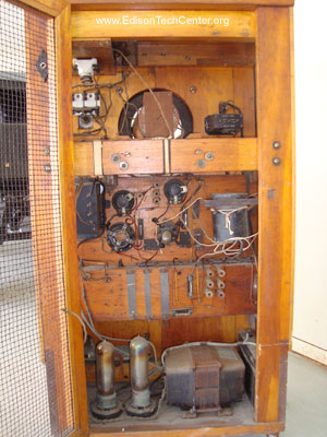
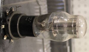
Video: The first loudspeaker prototype, this video shows you the tubes used in this 1921
prototype.
Types of amplifiers:
Operational Amplifiers
Differencial Amplifiers
Isolation Amplifiers
Negative Feedback Amplifiers
Instrumentation Amplifiers
Further Reading:
Transistor Theory >
Operational Amplifiers >
Semiconductor Electronics >
Radio >
Related Topics:
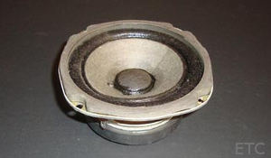
Loudspeakers |
Vacuum Tubes |
Microphones |
Television |
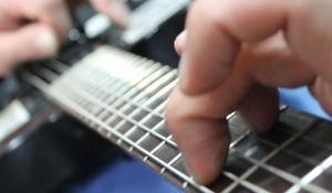
Electric Guitars |

More Stuff |
Article by M.W.
Sources:
Ernst Werner von Siemens. FamousScientists.org
Greenmountainaudio.com
Understanding the Basics of Electronics Circuits. by Gordon McComb and Earl Boysen. 2005
Interview with Corbin Irvin. Edison Tech Center. 2013
Microwave Processing of Materials. National Academy Press. 1994
How Tube Amplifiers Work. Uncle Doug. 2014
What is Microphone Bias Voltage?. LearningAboutElectronics.com
Photos:
Edison Tech Center
For use of Edison Tech Center images and videos see our licensing agreement.